Hacking the Tedsen SunTed®433 MHZ Window Controllers
When smart buildings go crazy, we need to fix it. For some time now I’ve been dealing with such an issue where a drop of rain hits a sensor, and suddenly my smart building raises my window. It’s annoying, especially when building caretakers don’t take the time to properly set the devices. The information presented here is a culmination of months of work, many equipment purchases, and finally a solution to the crazy smart building, keeping the window where I want it.
Establish the Specifications
The first step to hacking these Tedsen SunTed® window controllers is to understand exactly which frequency they are transmitting on, and then to understand their modulation scheme. A HackRF One module, by Great Scott Gadgets was acquired, and the Universal Radio Hacker (URH) software was downloaded for this task. I can’t say that either are easy to use, so it took many trials and errors to understand how to configure everything so that I could capture a proper signal, and then repeat the transmission to confirm a good capture. Through this research, I found that the transmitters operate on the 433.920 MHz frequency, using Amplitude Shift Keying (ASK) as their modulation scheme.
Find a Suitable RF Module and Controller
Since the HackRF One is an expensive unit, and there are cheap 433.92 MHz transmitters available, I decided to work out a solution using an Arduino Nano and a cheap 433.92 MHz transmitter. What’s important to note is that this is a “dumb” transmitter; i.e., it sends whichever data you send to it; no special software library is required to interface with the device, making it a dream to work with.
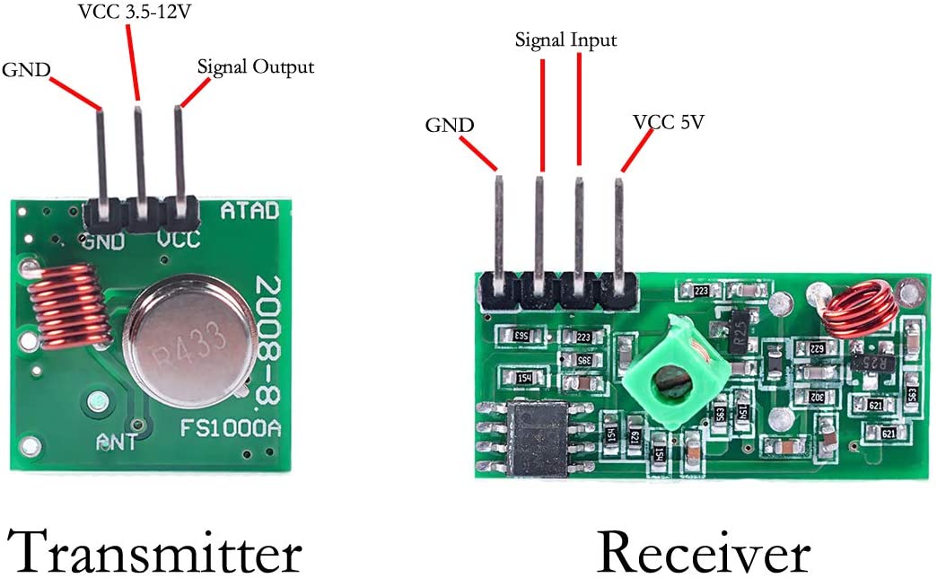
Note that I didn’t create these images, and “Signal Output” is actually “Data Input” from the Arduino.
Write the Arduino Code to Control the SunTed® Window
What I understand about these SunTed® controllers is that they are addressable, and do not implement a rolling code, which makes writing the code so much easier! However, as I had a lot of trouble using various Arduino libraries with the device, I decided to write my own, library-free, code to control the window. However, I’ve never written a time-specific piece of code for Arduino, so I wasn’t sure I could get the timing right. The simplicity of Arduino did not disappoint, and it turns out the code worked on the first try–which sent me into a rage of maniacal laughter, as I realized I now had full control over this window that gave me so much trouble before.
To save you the trouble of deciphering the protocol on your own, I present my Arduino code here, which spells out the specific timing required for the window receiver to decode it properly, as a state machine using a bit banging scheme. You only need to provide the “downBitData” and “upBitData” as an array of boolean values.
const unsigned int bangPin = 12; //This is the pin the data is being sent to the transmitter on
const unsigned int zeroPulseOn = 700; //microseconds; the mark to indicate a zero bit
const unsigned int logicLength = 4; //milliseconds; the length of the bit after the mark
const unsigned int bitSpace = 500; //microseconds; the space between two bits when going from 1 to 1
const unsigned int preambleDelay = 600; //microseconds; the delay betweeen preamble bits
const unsigned int timeBetweenFrames = 33; //milliseconds; the time between sending another frame
const unsigned int replayQty = 4; //quantity; how many times the data frames should be sent

//Down: 011100110000111011101110101010 00011000001010
//Up:   011100110000111011101110101010 10101111001001

bool downBitData [] {
  0,1,1,1,0,0,1,1,0,0,0,0,1,1,1,0,1,1,1,0,1,1,1,0,1,0,1,0,1,0,0,0,0,1,1,0,0,0,0,0,1,0,1,0
};
bool upBitData [] {
  0,1,1,1,0,0,1,1,0,0,0,0,1,1,1,0,1,1,1,0,1,1,1,0,1,0,1,0,1,0,1,0,1,0,1,1,1,1,0,0,1,0,0,1
};

void setup() {

  pinMode(bangPin,OUTPUT);

  pinMode(LED_BUILTIN, OUTPUT);

}

void loop() {

  digitalWrite(LED_BUILTIN, HIGH);

  transmitData(downBitData,sizeof(downBitData));

  //transmitData(upBitData,sizeof(upBitData));

  digitalWrite(LED_BUILTIN, LOW);

  delay(500);

}

void transmitData(bool *bitData, unsigned int dataSize){

  preAmble();

   for(unsigned int j = 0; j < replayQty; j++){

     for(unsigned int i = 0; i < dataSize; i++){

        if(bitData[i] == true){

          onePulse();

        }else{

          zeroPulse();
        }
     }

     delay(timeBetweenFrames);
   }

   delay(timeBetweenFrames);
}

void preAmble(){

  digitalWrite(bangPin, HIGH);
  delayMicroseconds(preambleDelay);
  digitalWrite(bangPin, LOW);
  delayMicroseconds(preambleDelay);

  digitalWrite(bangPin, HIGH);
  delayMicroseconds(preambleDelay);
  digitalWrite(bangPin, LOW);
  delayMicroseconds(preambleDelay);

  digitalWrite(bangPin, HIGH);
  delayMicroseconds(preambleDelay);
  digitalWrite(bangPin, LOW);
  delayMicroseconds(preambleDelay);

  digitalWrite(bangPin, HIGH);
  delayMicroseconds(preambleDelay);
  digitalWrite(bangPin, LOW);
  delay(timeBetweenFrames);

}
void zeroPulse(){

  digitalWrite(bangPin,HIGH);
  delayMicroseconds(zeroPulseOn);
  digitalWrite(bangPin,LOW);
  delay(logicLength);

}

void onePulse(){

  digitalWrite(bangPin,HIGH);
  delay(logicLength);
  digitalWrite(bangPin, LOW);
  delayMicroseconds(bitSpace);

}
The beauty lies in the code and circuit simplicity. The code can be expanded to include, for example, a rain sensor, wind sensor, temperature and humidity sensor, etc. Or, maybe add an up and down button to control the direction? For my use, I only care that when the device is powered on, it keeps the window in the down position, and for me, this does the trick.
Technical Details
So that you know that I actually did this work, here’s how I decoded the protocol:
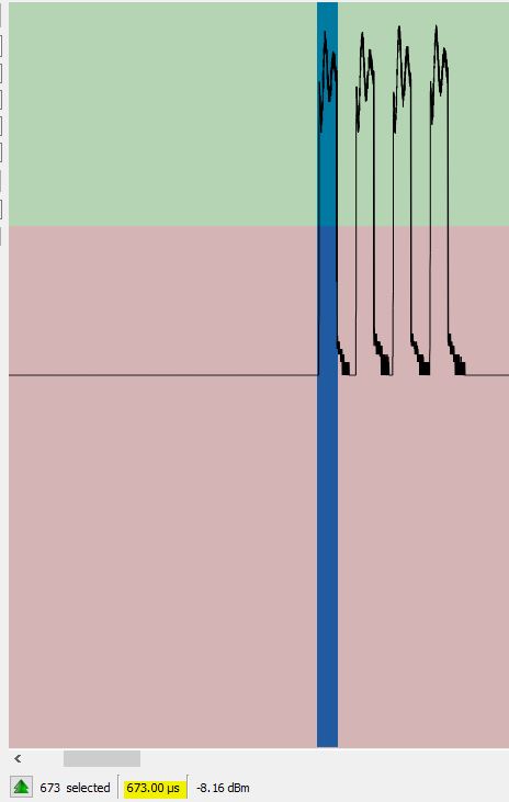
Preamble
The preamble, or synchronization frame, are four bits spaced approximately 600 microseconds wide, spaced by 600 microseconds. The URH software allows an easy check of the bit spaces. Note: that such measurements are not accurate; you’re seeing a representation of the bits, not an accurate measurement, so we must make some assumptions when doing this type of work. I selected 600 microseconds and it works.
Data Logic HIGH and Logic LOW Representation
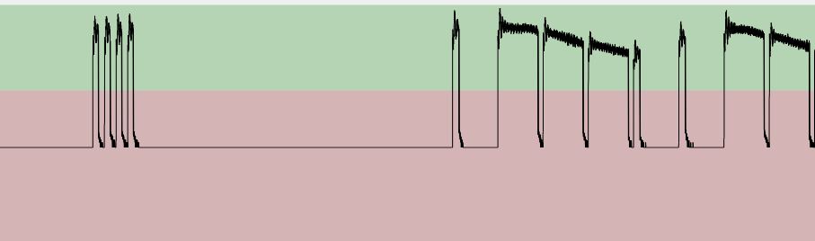
The URH software, by default, gets it wrong as to what is a 1, or logic HIGH, and logic LOW. So, you actually have to implement your own substitution mask where a 1 is represented as 111111110 and a 0 is represented as 100000000. Additionally, the first 8 bits, the preamble, are cut away. In my case, there were 40-bits of data per data frame, and there were four data frames, spaced approximately 33 milliseconds apart, with precisely the same data.
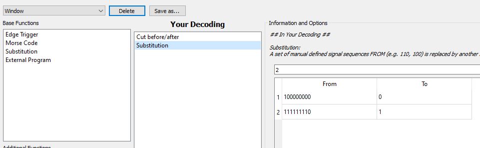
What we’re left with is the correct data sent from the Tedsen SunTed transmitter, and these are the data we enter into the Arduino code, comma-delimited, for “downBitData” or “upBitData”.
In addition to the URH analysis, I also probed the Tedsen microcontroller with a logic analyzer, which I built from a Papilio Pro FPGA and OLS logic analyzer software, via the Papilio DesignLab, which confirmed the correct bit stream.
What does a Logic HIGH and Logic LOW look like in URH for the Tedsen SunTed Transmitter?
To get the best understanding, I look at a Logic HIGH first. Here, we see that the amount of time a logic HIGH is on, is about 4 milliseconds. Then, to distinguish between two bits of Logic HIGH, there’s a small space where logic is low. That space is approximately 600 microseconds long.
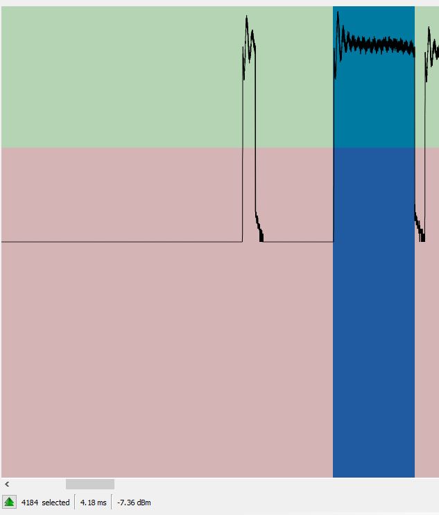
So, it follows that a logic LOW will be also about 4 milliseconds long, with a 600 microsecond space.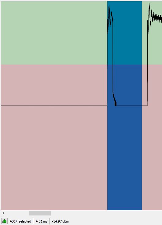
Conclusion
Presented here is a proof of concept showing how to control a Tedsen SunTed window using cheap components readily available on the open market, and the analysis of the signal. The code is provided without warranty or support, and you’re welcome to use it both commercially and otherwise.
It all started when I watched my dad fix a very expensive RC car after I ran it to death, when I was a kid.