I have heard a lot of great things about DDS chips and my research on them shows that, over the recent years, these chips have become more advanced to the point where they can work well as a low noise, good spurious-free dynamic range [SFDR], variable frequency oscillator [VFO] [aka Numerically Controlled Oscillator, NCO].
I have a specific application that I’d like to use a DDS VFO in, but due to the nature of it, I cannot release that project right now. In lieu of that, and in an effort to provide the open source community with something to work with, and further my portfolio here, I’ve decided to create a general Arduino shield and library for the AD9951 that I can release.
While using an Arduino with the AD9951 shield is not the best way to do this, the shield is intended to be an introduction to these chips. I can see where it may benefit an end user to use a CPLD or FPGA in lieu of the slow Arduino, especially to take advantage of the 25MHz maximum clock on the serial interface of the AD9951–the maximum serial clock available on the Arduino Mega 2560 R3 is 8MHz. Having a faster serial clock means that the phase offset word [POW] and frequency tuning word [FTW] can be updated quicker so faster phase modulation and faster frequency hopping, or even frequency modulation, which translates to more data transfer, if that is the goal.
Reading over the datasheet for the AD9951 DDS chip by Analog Devices Inc., one can become both overwhelmed and confused. The datasheet is not written as well as the datasheets for some of the other chips from this company, in my opinion, so a lot of experimentation will need to take place in order to understand this chip more fully. For example, the datasheet describes the Amplitude Ramp Rate [ARR] with “The ARR register stores the 8-bit amplitude ramp rate used in the auto OSK mode“, but it doesn’t provide an example of what the ARR is. In other words, if I set this register to 127, what does 127 mean? Does it mean that it will take 127uS to ramp? Does it mean I will eat 127 donuts this year? Who knows? There are so many questions, which only makes me want to get this shield completed so that I can experiment and learn more about this chip. Know that I will post my full findings and explanation about each of the registers as they exist in real life.
Shield:
On April 16, 2014, I sent off the shield final design to the fabricator. Here are some screenshots of the board courtesy of OSHPark.
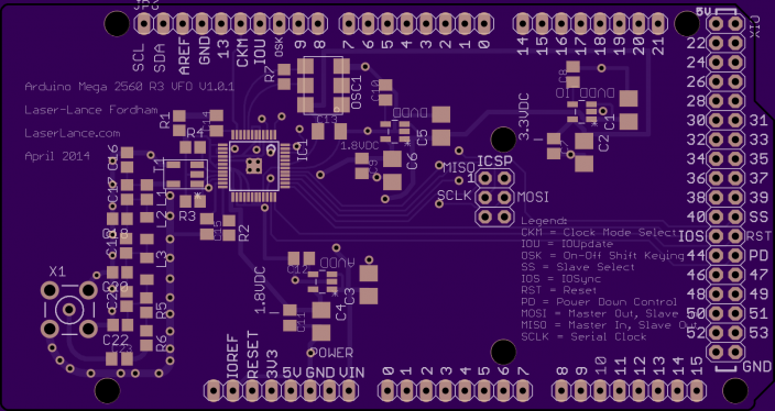
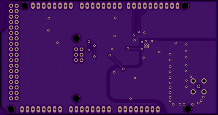
-
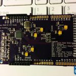
- Assembled Arduino VFO/NCO AD9951 Board

Library:
It took me about an hour to write a basic library that would give the user as much flexibility as possible, but I’d like to improve the library so that more automatic functions are available. This release is very much a beta release and is completely untested since I don’t yet have a shield. The examples are not even complete. Why am I releasing this then? Because there’s probably some poor soul who is just as overwhelmed as I am trying to figure out this chip so by seeing how I am implementing things, they may understand the chip a little better. Or maybe we can collaborate? One thing I think people will find about my code is that I write it as someone would like to read it; I don’t use fancy shortcuts that a novice may not understand if I can help it.
UPDATE May 24, 2014:
I have been pretty busy with projects from work so it has taken me a while to assemble this shield and provide an update here. First thing: the code that was provided here pre April was absolutely wrong! I have updated the code, and I have confirmed with my assembled shield that it works to the extent that I can get the AD9951 to change frequencies. This means that the instantiation and configuration code, also works. I have not put a lot of time into the code, however, so it is still quite sparse. This is a project that interests me so I will do as previously promised and eventually provide all of the details that I can about this great device.
I will also be releasing the circuit boards for purchase. Unfortunately, I do not have time to assemble kits and such, so I will only provide an unpopulated circuit board, the schematic [PDF], the board layout [PDF], the Arduino-compatible library, and a complete BOM [XLS] with vendors and vendor part numbers. I have no idea what kind of price I would put on this at this time since I just came up with the idea to sell the boards as I was writing this, but if you’re interested in building one of these then please contact me. My email address is at the top of the .cpp file in the library. Well, I had good intentions, but the brain thinks faster than the human can work, unfortunately. You can get the board from OSH Park if you wish.
Why am I not providing Eagle files? I don’t want to do anybody’s homework for them. However, if you contact me from a non-free email address then I will consider sending these files along.
UPDATE September 7, 2014:
I have finally had a chance to sit down with my AD9951 shield and my oscilloscope to see just what this fancy chip can do. As previously mentioned, I wanted to understand the Amplitude Ramp Rate since my application will depend on some sort of keying suppression. What I found was really disappointing; the shortest duration of on/off time of the Amplitude Ramp Rate, which is setting this register to 0x01, is approximately 100uS with my setup–I’m using a 400MHz oscillator without any of the PLL functions. I really need for this value to be in the neighborhood of 10uS, unfortunately. If you need a nice long ramp when performing On Off Shift Keying [OSK], then this function will work nicely since the maximum is 0xFE.
One thing to note when configuring this device for OSK is that if you set bits 13:0 of the ASF register to a very low number then the overall amplitude of the signal will also be very low. The highest value that can be selected, to give the highest amplitude, is 16383. I had initially set the ASF register to 0, which made me wonder why I wasn’t getting a signal at the output.
I am very pleased with how this device is performing and I can see where it will fit the bill in many different circuits that I’m interested in.
UPDATE April 12, 2017:
The BOM and Schematic for this board have been added to the download section below.
Download:
May 24, 2014: Arduino Library for Analog Devices AD9951 DDS V 1.0.0B
April 12, 2017: Arduino_VFO_V1.0.1 Schematic
April 12, 2017: Arduino_VFO_V1.0.1 BOM
9 Responses
Hi, This board is just what I have been looking for – ordered from OSH PARK – do you have the schematic you could email me please?
73 Phil zl3pah
Hi Phil,
Yes, I will send the schematic and BOM momentarily. I have also updated the web page to include these items.
I have search all over the place for something like this. It’s 2016 but last comments were a year ago. Hope it’s not too late to get a board/kit to begin with my Mega 2560 Arduino.
Thanks for all the fine work you did. otherwise, us newbies would always be in the dust. We are anyway, one might argue.
Hi Bill,
Thank you for your comments. I am still around, but I stay incredibly busy with work so I only have a limited amount of time to work on these projects. I have actually been working on a dual DDS shield for Arduino, and I have not yet decided if I want to create a production board with a single DDS chip or not. While the single DDS shield offers a lot of flexibility, a dual DDS adds even more capabilities in terms of what can be done with the Arduino. Add to the limited functionality of the single chip, the cost of the shield, and I don’t know if someone is willing to pay about $125 for a board that only offers one output up to 200MHz. Combine the selling of these boards with also needing some way to support them, and the task becomes daunting with my current state of affairs, unfortunately.
[…] Arduino VFO/NCO using an AD9951 DDS, Shield and Library […]
Hey, I saw your boards on oshpark and went looking for your blog page. When you get to selling the boards, let me know. I’d be down for one, maybe two. Guess I could just order the three from OSH too. Let me know.
Hi John,
Yes, I think I did share these boards on Oshpark. At this time, I don’t have the time to do anything in terms of selling and such. I also gave away my last board to someone a couple of months ago so I don’t have any on hand. If you’d like the board, then it’s probably best to get it from Oshpark. I think I may have the BOM and schematic laying around that I can send to you, too. I will try to get that to you this weekend. Take care.
Lance.
Hi John,
I have added the BOM and Schematic to this page if you are still interested in it.
I want build oscillator use ad9951 with arduino, do you want give me the ways how to make it?